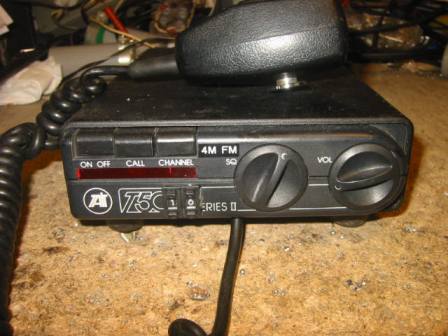
The Tait T500 series of PMR sets are now commonly available through various outlets (Ebay etc.) at low prices; I recently bought three T525 sets for a total of £20.00. The 500 series radios are a high performance two channel FM synthesised mobile radio transceiver which operate in the VHF to UHF bands, the T525 is designed for VHF low band use (68 – 88 MHz) and is easily converted to 4M amateur band. Using a CB channel switch or a BCD thumbwheel switch these sets will cover all FM channels in the amateur band.
The heart of the set is the frequency synthesiser integrated circuit (a MC145152p) which is a parallel programmed PLL. The chip requires a sixteen bit binary word for frequency acquisition, this is easily achieved by use of two small eproms (I used two 2732’s but more modern ones can be used). Each eprom contains eight of the required bits for each channel programmed.
You could use a single eprom and a couple of shift registers to give the same results (indeed, Tait produce a Marine band version of their T535 highband VHF set using this method), however in this instance I think it is a little easier to use the two eproms.
The conversion itself is fairly straight forward. Firstly the radio has to be tuned to the 4m band; this should be done before the conversion is implemented. Programme the original diode matrix board on channel one for a receive and transmit frequency of 70.300 MHz, the A and N division ratios for this frequency are given at the end of this article. Next the VCO has to be set up for this frequency: using a non inductive trimmer tool adjust the Rx VCO capacitor for a voltage of 3.5 volts at TP2/2. Now key the PTT (be sure to have a dummy load connected) and adjust the Tx VCO capacitor for a voltage of 3.5 volts at TP2/2. A
service manual and circuit diagram is available to help location of test points and components. Audio/regulator circuit diagram
Now to tune the PA strip. Bridge links 1 and 3 in the PA strip for operation below 77 MHz. Key the PTT and adjust CV254 and CV287 for maximum output into the dummy load. After adjustment, a power output of 25 Watts should be obtained for a current drain of no more than five amps (providing the power control preset, RV256, is set to maximum). Set the power control preset for an output of 20 Watts, this will allow long overs without the PA getting too hot. To disable the timeout on TX remove R17. Now the PA alignment is now complete. To tune the receiver use a signal generator and adjust L11, 12, 13, 14 and15 for best signal to noise ratio, start with the generator output high and reduce as sensitivity is improved. When complete you should be able to receive a -120dBm (0.22uV) signal with just a little background hiss (these radios are very sensitive). Be sure to use a suitable adjustment tool as the cores in the inductors are easily broken! Looking at the eprom board circuit diagram you will see it is very simple. eprom board circuit diagram in pdf format
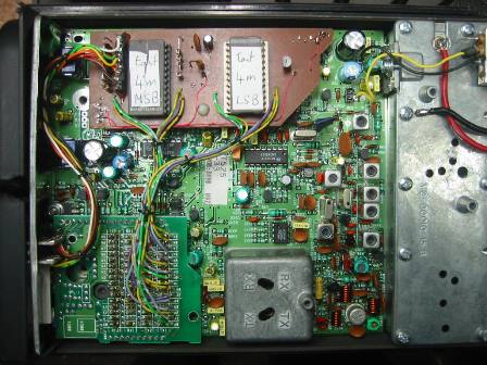
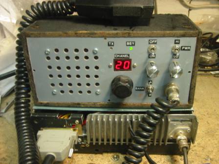
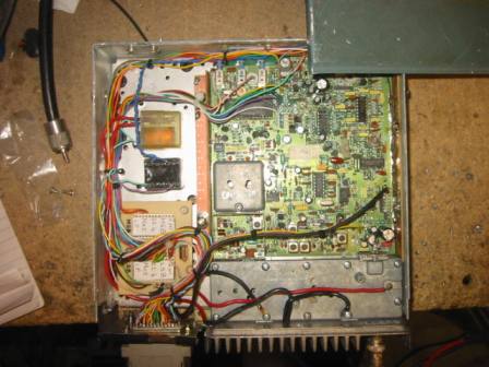
One eprom contains the first eight most significant bits and the other contains the remaining eight least significant bits. The eprom addresses are connected in parallel to the BCD switch (or CB switch). Tx data begins at address 0000 and Rx data begins at address 0800 (when using a 2732 eprom). Eprom address line A11 is normally held high thus accessing Rx data, but is pulled low when the PTT is keyed thus accessing Tx data. Using 2732 type eproms several hundred channels can be programmed providing you have a large enough BCD switch, however we only need 19 to cover the 4m FM band, channel 16 is programmed as the calling channel (70.450 MHz) and increments in 12.5 KHz steps up to channel 19 and also decrements in 12.5 KHz steps down to channel 1. I made a small PCB to contain the eproms etc. and fitted it where the CTCSS tone board was located (see pics). Vero board would be a good substitute for a PCB. A suitable size hole was cut into the front panel of the radio to house the BCD switch, this was glued in place as it had no locking tabs. The original channel one/two switch is utilised as a power control switch: in channel one position this is high power (20 Watts) and channel two position is low power (5 Watts – suitable for driving a QQV06-40A to 100 Watts continuous, see my Pye AM valve base station conversion). Connections to N9 – N0 and A5 – A0 in the synthesiser were made via the diode matrix board (see photo); make sure you remove all diode bridges on this board before you connect N9 – A0. Power, ground and PTT where routed through the original tone board connections. Shown in the photographs is a two metre version (using a T535) with a CB switch mounted in a control head along with all user controls and a speaker, the radio chassis is mounted in an old Westminster case connected via an umbilical to the control head. This was done because the radio case was badly smashed. Channel 01 to 07 are R1 to R7 (repeaters) and 08 to 23 are S8 to S23 (simplex) and 40 is R0, this makes the switch tie directly with the channels. Using eproms in this way is not new by any means but it is a solid and simple way to control the PLL chip. So, there you have it, for a small financial outlay and a little effort you will have a very good performance 4m FM radio. For those not familiar with these radios, the Tx modulation is excellent as is the Rx audio and selectivity. Four metre activity here in the Midlands is good. There are regular Coventry and Wolverhampton nets and regular Birmingham nets also. Most equipment used on 4m is PMR as there are not too many commercial manufactures producing radios for this band. A hex dump is included here for both eproms (MSB and LSB) for 4m and also for 2m.
Diode matrix configuration for initial tune up on 70.300 MHz; TX bridge N9, 7, 6, 5, 2, 1, 0, A3, 2, 1, 0. RX bridge N9, 7, 5, 4, 3, 1, 0, A5, 4, 3, 2, 1, 0. All other pads or diodes left open.
4m MSB eprom code
4m LSB eprom code
2m MSB eprom code
2m LSB eprom code


The two photographs on the right show the 2m conversion, the Tait t530 PCB is mounted in an old Westminster case.The control head is connected to the radio via an umbilical using some multicore cable and a couple of 25 pin D-connectors. The two eproms can just be seen in the lower left of the case.

Barry Zarucki M0DGQ HOME